SEPM Question Bank CAE-2 with Answers
Questions
Discuss various objectives of system design along with principles.
Give the different types of architecture styles.
What is the necessity of architecture?
Give the classification of UML diagrams.
Elaborate the different diagrams involved in structural diagrams.
Elaborate the different diagrams involved in behavioral diagrams.
Give the different ways of designing to interact modules in the system.
Analyze the different types of relationships in system design.
Write short notes on: a) Class diagram b) Activity Diagram.
Explain the concept of Dependency with its different types.
Discuss the concept of aggregation, generalization, association.
Explain the various phases of STLC.
Discuss the concept of verification and validation.
Describe the various types of software testing.
Give the various approaches of Black box testing.
Discuss the various techniques of White box testing.
Elaborate on functional and nonfunctional testing.
Discuss the format of test cases for any application.
Discuss Regression testing and various types of functional testing.
1.Discuss various objectives of system design along with principles
Ans1
System design is a critical phase in the software development process, aiming to transform the functional requirements of a system into an architectural blueprint. The following objectives guide the system design process:
-
Efficiency: The system should be designed to execute tasks and processes efficiently, minimizing resource usage, and ensuring optimal performance.
-
Scalability: The design should allow the system to handle increased workloads and growth without a major overhaul.
-
Reliability: The system should be reliable, ensuring consistent and error-free operation. It should minimize downtime and disruptions.
-
Maintainability: The design should be easy to maintain and update. Code should be modular, well-organized, and well-documented to facilitate future modifications.
-
Security: The system should incorporate security measures to protect data, prevent unauthorized access, and defend against threats.
-
Usability: The design should prioritize user experience, ensuring that the system is user-friendly and intuitive.
-
Flexibility: The system should be flexible enough to accommodate changing requirements and adapt to evolving technologies.
-
Interoperability: When necessary, the system should be designed to integrate seamlessly with other systems and technologies.
-
Cost-Effectiveness: The design should consider cost constraints, aiming to deliver value within budgetary limits.
-
Compliance: If applicable, the system should comply with industry standards, regulations, and legal requirements.
Several principles guide effective system design:
1. Modularization
- Principle: Divide the system into smaller, manageable modules or components.
- Rationale: Modularity simplifies development, maintenance, and testing. Each module has a specific responsibility.
2. Abstraction
- Principle: Hide unnecessary details and expose only relevant information to users or other modules.
- Rationale: Abstraction simplifies complexity, making the system more understandable and manageable.
3. Encapsulation
- Principle: Bundle data and methods that operate on that data into a single unit (e.g., a class).
- Rationale: Encapsulation promotes data integrity and protects data from unauthorized access.
4. Cohesion
- Principle: Ensure that elements within a module are closely related and have a single, well-defined purpose.
- Rationale: High cohesion improves module readability and maintainability.
5. Loose Coupling
- Principle: Minimize dependencies between modules so that changes in one module don't heavily impact others.
- Rationale: Loose coupling enhances system flexibility and reduces the risk of unintended consequences.
6. Separation of Concerns (SoC)
- Principle: Divide the system into distinct sections, each addressing a specific concern or aspect.
- Rationale: SoC simplifies development, testing, and maintenance by isolating concerns.
7. Single Responsibility Principle (SRP)
- Principle: Each module or class should have only one reason to change.
- Rationale: SRP promotes code maintainability and makes it easier to identify and fix issues.
2.Give the different types of architecture styles
Ans2
-
Client-Server Architecture:
- Separates the client (user interface) and server (application processing) components.
- Allows for scalability and easier maintenance.
-
Microservices Architecture:
- Decomposes applications into small, independent services.
- Promotes flexibility, scalability, and ease of development.
-
Monolithic Architecture:
- All components of an application are tightly integrated into a single codebase.
- Simplicity but may lack scalability and flexibility.
-
Service-Oriented Architecture (SOA):
- Organizes applications as a set of services that can be accessed and combined.
- Encourages reusability and interoperability.
-
Event-Driven Architecture:
- Components communicate by triggering and reacting to events.
- Enables real-time processing and decoupling of systems.
-
Layered Architecture:
- Separates an application into distinct layers (e.g., presentation, business logic, data).
- Enhances modularity and maintainability.
-
Peer-to-Peer (P2P) Architecture:
- All nodes in the network have equal status and can act as both clients and servers.
- Common in decentralized systems like file sharing.
-
Component-Based Architecture:
- Constructs an application from reusable software components.
- Promotes modularity and reusability.
-
Container-Based Architecture: - Uses containers (e.g., Docker) to package and deploy applications with their dependencies. - Streamlines deployment and scaling.
-
Serverless Architecture: - Focuses on writing code (functions) without managing server infrastructure. - Scales automatically based on demand.
3. What is necessity of architecture
Ans3
The necessity of architecture in any context, including software or construction, can be summarized as follows:
-
Planning and Organization: Architecture provides a structured plan for the design and development of complex systems or projects. It outlines the components, relationships, and objectives, ensuring that everyone involved has a clear understanding of the project's direction.
-
Efficiency and Optimization: Architecture helps in optimizing resources and processes. It ensures that resources like time, budget, and manpower are utilized efficiently to achieve the desired outcomes.
-
Scalability: An architectural design considers scalability, allowing a system or project to grow and adapt to changing requirements or demands without requiring a complete overhaul.
-
Maintainability: Architectural decisions often contribute to the ease of maintaining and updating a system or structure over time. It allows for easier troubleshooting, bug fixes, and enhancements.
-
Risk Management: By defining an architecture upfront, potential risks and challenges can be identified and addressed early in the project, reducing the likelihood of costly issues later.
-
Communication: Architecture serves as a common language for stakeholders, facilitating effective communication among project teams, clients, and decision-makers.
-
Quality Assurance: It sets the foundation for quality control and assurance processes. A well-designed architecture can lead to a higher-quality end product.
-
Alignment with Goals: Architecture ensures that the project aligns with the overall goals and objectives, preventing deviations that may lead to wastage of resources.
4. Give the classification of UML diagram
Ans4
UML Diagram
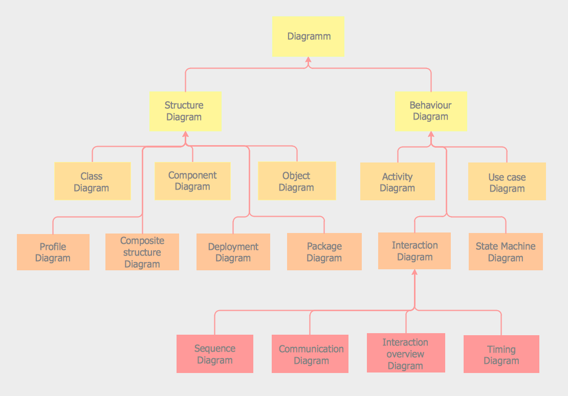
-
Structural Diagrams:
- Class Diagram: Represents the static structure of a system, including classes, attributes, associations, and their relationships.
- Object Diagram: Shows a snapshot of objects and their relationships at a specific point in time.
- Component Diagram: Illustrates the physical components of a system and their dependencies.
- Deployment Diagram: Focuses on the physical deployment of software components on hardware nodes.
- Package Diagram: Organizes elements into packages to depict the high-level structure of a system.
- Composite Structure Diagram: Describes the internal structure of a class and how its parts collaborate.
-
Behavioral Diagrams:
- Use Case Diagram: Represents the interactions between actors (users) and a system to define its functionality.
- Activity Diagram: Depicts the workflow or activities within a system, often used for business processes.
- Sequence Diagram: Shows the interactions and order of messages between objects over time.
- Communication Diagram: Emphasizes the interactions between objects but with a focus on relationships and links.
- State Machine Diagram: Models the states and transitions of an object or system, often used for behavior modeling.
- Timing Diagram: Represents the timing constraints and interactions between lifelines in a system.
5. Elaborate the different diagram involved in structural diagram
Ans5
Structure diagrams depict the static structure of the elements in your system, such as how one object relates to another. They represent the things in the system, including classes, objects, packages or modules, physical nodes, components, and interfaces. These diagrams are extensively used in documenting the software architecture of software systems, similar to how the static aspects of a house encompass the existence and placement of walls, doors, windows, pipes, wires, and vents.
The Seven UML structural diagrams are roughly organized around the major groups of things you'll find when modeling a system.
| Structural Diagram | Brief Description |
|---|---|
| Composite Structure Diagram | It shows the internal structure of a classifier, classifier interactions with the environment through ports, or behavior of a collaboration. |
| Deployment Diagram | It shows a set of nodes and their relationships that illustrate the static deployment view of an architecture. |
| Package Diagram | It groups related UML elements into a collection of logically related UML structures. |
| Profile Diagram | Profile diagram, a kind of structural diagram in the Unified Modeling Language (UML), provides a generic extension mechanism for customizing UML models for particular domains and platforms. |
| Class Diagram | It shows a set of classes, interfaces, and collaborations and their relationships, typically found in modeling object-oriented systems. |
| Object Diagram | It shows a set of objects and their relationships, which are static snapshots of instances found in class diagrams. |
| Component Diagram | It shows a set of components and their relationships that illustrate the static implementation view of a system. |
6. Elaborate the different diagram involved in behavioral diagram
Ans6
UML's five behavioral diagrams are used to visualize, specify, construct, and document the dynamic aspects of a system. They show how the system behaves, interacts with itself and other entities (users, other systems), how data moves through the system, how objects communicate, how time affects the system, and what events cause internal state changes. These diagrams are extensively used to describe the functionality of software systems.
Behavioral diagrams illustrate how the system works 'in motion,' including its interactions with external entities and users and how it responds to input or events under certain constraints. There are seven behavioral diagrams that model the dynamics of a system:
| Behavioral Diagram | Brief Description |
|---|---|
| Activity Diagram | It is a graphical representation of workflows with stepwise activities, actions, and support for choice, iteration, and concurrency. |
| Use Case Diagram | It describes a system's functional requirements in terms of use cases, enabling the relationship between system needs and how they are fulfilled. |
| State Machine Diagram | It shows the discrete behavior of a part of a designed system through finite state transitions. |
| Sequence Diagram | It shows the sequence of messages exchanged between objects to carry out the functionality of a scenario. |
| Communication Diagram | It shows interactions between objects or parts represented as lifelines using sequenced messages in a free-form arrangement. |
| Interaction Overview Diagram | It depicts a control flow with nodes that can contain other interaction diagrams. |
| Timing Diagram | It shows interactions when the primary purpose is to reason about time by focusing on conditions changing within and among lifelines along a linear time axis. |
7. Give the different ways of design to interact modules in the system
Ans7
-
Loose Coupling: Design modules with minimal dependencies on each other. Use interfaces or APIs to define how modules interact, allowing for flexibility and easy replacement of components.
-
High Cohesion: Group related functions and data within modules to ensure that each module has a clear and specific purpose. This promotes maintainability and reduces unintended side effects.
-
Publish-Subscribe Pattern: Implement a publish-subscribe mechanism where modules can publish events or messages, and other modules can subscribe to receive and respond to those events.
-
Dependency Injection: Pass dependencies required by a module as parameters rather than having the module directly reference them. This reduces coupling and makes modules more testable.
-
Service-Oriented Architecture (SOA): Organize the system into loosely coupled services that communicate through standardized interfaces, such as RESTful APIs or messaging protocols.
-
Model-View-Controller (MVC): Divide the system into three components: Model (data and business logic), View (user interface), and Controller (mediator between Model and View). This separation facilitates modularity and maintainability.
-
Middleware: Use middleware layers to handle communication and interaction between modules. This approach abstracts the underlying communication details and allows modules to focus on their core functionality.
-
Message Queues: Implement message queue systems like RabbitMQ or Apache Kafka to enable asynchronous communication between modules, enhancing scalability and fault tolerance.
-
Event-Driven Architecture (EDA): Design the system to respond to events generated by modules. Modules can subscribe to relevant events and react accordingly, allowing for flexibility and decoupling.
-
RESTful APIs: Define clear and RESTful APIs for modules to communicate over HTTP. This approach simplifies integration with external systems and promotes a uniform interface.
-
Plug-ins and Extensions: Allow modules to be extended or customized through plug-ins or extensions. This enables third-party developers to add functionality without modifying the core system.
-
Microservices: Break the system into small, independent microservices, each responsible for a specific functionality. Microservices communicate through well-defined APIs or messaging.
8. Analyze the different types of relationships in the system design
Ans8
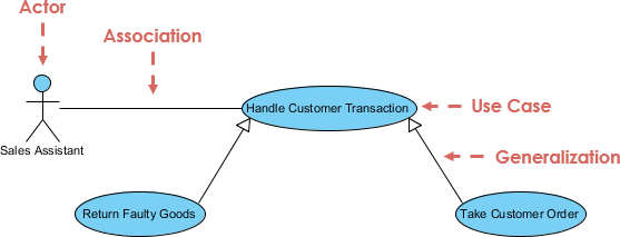
In the context of Unified Modeling Language (UML), use cases can be interconnected using various relationships or connectors to represent the flow of interactions and dependencies between them. These relationships help provide a more comprehensive understanding of how different use cases within a system or software application are related and how they collaborate.
Let's explore some of the common types of relationships among use cases:
-
Association Relationship: An association relationship shows that two or more use cases are related or associated with each other in some way. It doesn't specify the direction of the interaction but indicates a general association. For example, if two use cases often occur together or share some common elements, you can represent this using an association relationship.

-
Include Relationship: The include relationship indicates that one use case includes another use case. This means that the included use case is a part of the main use case and is essential for its execution. The inclusion relationship is often used to represent shared or reusable functionality. For instance, a "Make Payment" use case might include an "Authenticate User" use case.
-
Extend Relationship: The extend relationship represents optional or conditional behavior that can extend the functionality of a base use case under specific conditions. It indicates that an extending use case can add extra behavior to the base use case if certain conditions are met. For example, an "Order Processing" use case might be extended by an "Apply Discount" use case if the user is eligible for a discount.
-
Generalization Relationship: In UML, generalization represents inheritance. When one use case generalizes another, it means that the generalized use case serves as a superclass, and the generalizing use case is a subclass that inherits its behavior. This relationship is often used to show how a more specific use case inherits characteristics from a more general one.
-
Dependency Relationship: Dependency relationships between use cases indicate that one use case relies on another, but it's not necessarily a direct association or inclusion. It signifies that a change in one use case may affect another. Dependencies can be used to represent indirect relationships and can be valuable for managing change impact.
Understanding and effectively using these relationships among use cases is crucial for modeling complex systems and applications accurately. These relationships help project teams and stakeholders visualize how different parts of the system interact, collaborate, and depend on each other, contributing to a better overall understanding of system behavior and architecture.
Here's a summary table of the common types of relationships among use cases, including when to use them:
| Relationship Type | Description | When to Use |
|---|---|---|
| Association | Indicates a general association between use cases. | When two or more use cases are loosely related or associated. |
| Include | Specifies that one use case includes another. | When one use case is essential for the execution of another. |
| Extend | Represents optional or conditional behavior. | When a use case may extend the functionality of another. |
| Generalization | Indicates inheritance between use cases. | When a specific use case inherits behavior from a general one. |
| Dependency | Shows reliance between use cases. | When one use case depends on another indirectly. |
9. Write short notes on a. Class diagram b. Activity Diagram
Ans9
Class Diagram
A Class Diagram is a type of UML diagram used to visualize and represent the static structure of a system. It provides an overview of the classes, interfaces, relationships, attributes, and methods in the system. Key points about Class Diagrams include:
- Classes: Represent objects or entities in the system. They contain attributes (data) and methods (functions) that define their behavior.
- Relationships: Show how classes are related to each other. Common relationships include associations, dependencies, generalizations, and compositions.
- Attributes: Represent the properties or characteristics of a class. They provide information about the state of objects.
- Methods: Define the operations or functions that can be performed by objects of the class.
- Inheritance: Depicted through generalization relationships, it signifies that one class inherits properties and behaviors from another, establishing an "is-a" relationship.
- Association: Represents a connection between classes, indicating that objects of one class are related to objects of another class.
- Multiplicity: Specifies how many objects participate in a relationship, such as one-to-one, one-to-many, or many-to-many.
- Aggregation and Composition: Describe relationships where one class contains or is composed of other classes, signifying a "whole-part" relationship.
- Visibility: Denotes the access level of attributes and methods, such as public (+), private (-), or protected (#).
Class Diagrams are valuable for designing and documenting software systems, providing a visual representation of the system's structure and relationships.
Activity Diagram
An Activity Diagram is a UML diagram used to model the flow of activities or processes within a system or business process. It is particularly useful for visualizing the dynamic behavior and sequential logic of a system. Key points about Activity Diagrams include:
- Activities: Represent tasks, actions, or processes that occur within the system. They can range from simple operations to complex workflows.
- Transitions: Show the flow of control between activities. Arrows indicate the sequence in which activities are executed.
- Decision Nodes: Represent decision points where the flow of control can take different paths based on conditions.
- Forks and Joins: Indicate parallel or concurrent execution of activities and their synchronization.
- Start and End Nodes: Mark the beginning and termination points of the diagram.
- Swimlanes: Used to group activities based on responsibilities, roles, or entities within the system.
- Guards: Conditional expressions that determine which path an activity takes at a decision point.
Activity Diagrams are commonly used in business process modeling, software design, and system analysis to depict workflows, business processes, and the dynamic behavior of systems.
10. Explain the concept of Dependency with its different types
Ans10
Dependency is a fundamental concept in software design that represents a relationship between two elements where one element relies on or is influenced by another. Dependencies help in understanding how different components or modules in a system interact and ensure that changes in one component do not negatively impact others. There are several types of dependencies in software design:
Types of Dependencies
-
Static Dependency:
- Description: Static dependencies are determined at compile-time or design-time and are based on the structure of the code.
- Examples:
- Class A uses Class B, indicating a static dependency from A to B.
- A module imports functions from another module.
- Implications: Changes in the depended-upon element may require recompilation or retesting of the dependent element.
-
Dynamic Dependency:
- Description: Dynamic dependencies are resolved at runtime and are based on the actual execution of the program.
- Examples:
- A method call to a function in another module during program execution.
- Dependency injection, where objects are provided at runtime.
- Implications: Changes in dynamic dependencies may not be detected until runtime and can lead to unexpected behavior.
-
Compile-Time Dependency:
- Description: Dependencies that are determined and resolved during the compilation phase.
- Examples:
- Including header files in C/C++ programs.
- Importing modules in languages like Python.
- Implications: Compile-time dependencies affect the build process and determine what needs to be included during compilation.
-
Runtime Dependency:
- Description: Dependencies that are resolved and established when the program is executing.
- Examples:
- Loading dynamic libraries or modules at runtime.
- Instantiating objects based on user input or configuration.
- Implications: Runtime dependencies can affect the behavior and performance of the running program.
-
Direct Dependency:
- Description: A direct dependency exists when one element explicitly depends on another.
- Examples:
- A class uses another class through a direct function call.
- A module imports specific functions from another module.
- Implications: Direct dependencies are clearly defined and easy to trace.
-
Indirect Dependency:
- Description: An indirect dependency exists when one element depends on another through a chain of dependencies.
- Examples:
- Class A depends on Class B, which in turn depends on Class C.
- A module imports Module B, which itself imports Module C.
- Implications: Indirect dependencies can be harder to trace and manage, and changes in intermediate dependencies can impact the final dependency.
Understanding the types of dependencies and managing them effectively is essential for designing modular and maintainable software systems. By identifying and documenting dependencies, developers can make informed decisions about code changes, updates, and refactoring.
Discuss the concept of aggregation, generalization, association
Ans11
Unified Modeling Language (UML) provides several types of relationships to depict the associations and connections between classes and objects within a system. Three important relationships are Aggregation, Generalization, and Association:
Aggregation
-
Description: Aggregation represents a "whole-part" or "has-a" relationship between classes or objects. It signifies that one class (the whole) contains or is composed of other classes (the parts). In an aggregation, the parts can exist independently of the whole.
-
Notation: In UML diagrams, aggregation is represented by a diamond shape on the end of a line connecting the whole to its parts.
-
Example: Consider a "Car" class that aggregates "Engine," "Wheels," and "Seats" classes. The car contains these components, but they can exist independently or be shared among multiple cars.
Generalization
-
Description: Generalization represents an inheritance relationship between classes, where one class serves as a superclass (parent) and another class as a subclass (child). The subclass inherits attributes and behaviors from the superclass. It signifies an "is-a" relationship.
-
Notation: In UML diagrams, generalization is depicted as an arrow pointing from the subclass to the superclass, with a solid line.
-
Example: If you have a "Shape" superclass and subclasses like "Circle" and "Rectangle," it implies that a circle is a type of shape, and a rectangle is a type of shape, inheriting properties from the "Shape" class.
Association
-
Description: Association represents a generic relationship between classes or objects. It indicates that instances of one class are somehow related to instances of another class. Unlike aggregation and generalization, association doesn't imply a specific type of relationship.
-
Notation: In UML diagrams, association is depicted by a simple line connecting two classes. Multiplicity (such as one-to-one, one-to-many, or many-to-many) can be specified to show how many objects participate in the association.
-
Example: In a library system, an association between the "Book" class and the "Author" class signifies that books are related to authors, but it doesn't specify the nature of the relationship.
12. Compare SDLC and STLC
Ans12
| SDLC | STLC |
|---|---|
| SDLC is mainly related to software development. | STLC is mainly related to software testing. |
| Besides development other phases like testing are also included. | It focuses only on testing the software. |
| SDLC involves a total of six phases or steps. | STLC involves only five phases or steps. |
| In SDLC, more members (developers) are required for the whole process. | In STLC, fewer members (testers) are needed. |
| In SDLC, the development team makes the plans and designs based on the requirements. | In STLC, the testing team (Test Lead or Test Architect) makes the plans and designs. |
| The goal of SDLC is to complete the successful development of software. | The goal of STLC is to complete successful testing of software. |
| It helps in developing good-quality software. | It helps in making the software defect-free. |
| SDLC phases are completed before the STLC phases. | STLC phases are performed after SDLC phases. |
| Post-deployment support, enhancement, and updates are included if necessary. | Regression tests are run by the QA team to check deployed maintenance code and maintain test cases and automated scripts. |
| The creation of reusable software systems is the end result of SDLC. | A tested software system is the end result of STLC. |
13. Explain the various phases of STLC
Ans13
STLC, or Software Testing Life Cycle, is a systematic and structured approach to software testing. It comprises several phases, each with its specific objectives and activities. The primary goal of STLC is to ensure the quality and reliability of the software being developed. Here are the key phases of STLC:

1. Requirement Analysis
-
Objective: In this phase, the testing team thoroughly reviews and analyzes the project requirements, specifications, and documentation to gain a clear understanding of what needs to be tested.
-
Activities:
- Identify the scope of testing.
- Understand the functional and non-functional requirements.
- Create a test plan outline.
- Define testing objectives and criteria.
- Identify potential risks and challenges related to testing.
-
Output: Requirement Traceability Matrix (RTM), Test Plan Outline.
2. Test Planning
-
Objective: Test Planning involves creating a detailed test plan that outlines the testing strategy, approach, resources, and schedule. It defines how testing will be carried out throughout the project.
-
Activities:
- Define the test objectives and scope.
- Identify test deliverables, including test cases and test data.
- Allocate resources, including test environment setup.
- Create a test schedule and timeline.
- Define test metrics and reporting mechanisms.
-
Output: Comprehensive Test Plan Document.
3. Test Case Development
-
Objective: This phase involves the creation of detailed test cases based on the requirements and test scenarios defined earlier. Test cases serve as a set of instructions for testers to execute during the testing phase.
-
Activities:
- Develop test cases with clear test steps, input data, and expected outcomes.
- Ensure test cases cover both positive and negative scenarios.
- Organize test cases into test suites.
-
Output: Test Cases Document.
4. Test Environment Setup
-
Objective: Setting up the test environment involves preparing the necessary hardware and software configurations that are required for testing. It ensures that the test environment mirrors the production environment as closely as possible.
-
Activities:
- Install or configure the necessary software.
- Prepare test data and test databases.
- Ensure compatibility of the test environment with the application under test.
-
Output: Ready-to-use Test Environment.
5. Test Execution
-
Objective: In this phase, the actual testing is performed according to the test plan and test cases. Testers execute the test cases, record results, and report defects, if any.
-
Activities:
- Execute test cases systematically.
- Record test results, including pass/fail status.
- Log and report defects with detailed information.
- Conduct regression testing when required.
-
Output: Test Execution Results, Defect Reports.
6. Test Cycle Closure
-
Objective: Test Cycle Closure is the final phase of STLC, where the testing team assesses the completion of testing activities and prepares test summary reports. It also includes evaluating the overall testing process and identifying areas for improvement.
-
Activities:
- Summarize test results and achievements.
- Create a Test Summary Report.
- Perform a review meeting to gather feedback.
- Identify lessons learned and improvements for future testing cycles.
-
Output: Test Summary Report, Lessons Learned Document.
These phases of STLC ensure that testing activities are well-planned, executed, and documented, leading to effective quality assurance and defect identification throughout the software development life cycle.
14. Discuss the concept of verification and validation
Ans14
Verification and Validation (V&V) are two critical processes in software development and quality assurance. They are distinct activities that aim to ensure the reliability, correctness, and quality of software systems. Let's explore these concepts:
Verification
Definition: Verification involves the process of evaluating documents, design, code, and programs to ensure that they adhere to specified standards, requirements, and guidelines. It is a static testing process that focuses on reviewing and checking the software artifacts without executing them.
Nature: Verification is considered a static testing process because it does not involve running the actual code. Instead, it aims to confirm that the software is built correctly according to its design and requirements.
Methods Used: Methods used in verification include reviews, walkthroughs, inspections, and desk-checking. These activities help identify issues, inconsistencies, or deviations in the early stages of development.
Objective: The primary objective of verification is to check whether the software artifacts (such as design documents and source code) conform to specifications, standards, and design guidelines. It ensures that the software is built correctly.
Bug Detection: Verification can find defects, errors, or discrepancies in the early stages of the development process. By identifying issues early, it helps prevent them from propagating into later phases.
Goal: The ultimate goal of verification is to assess the software's architecture and specification to ensure that it aligns with the intended design and requirements.
Responsibility: Verification is typically carried out by the quality assurance team and involves peer reviews and inspections.
Validation
Definition: Validation is the process of evaluating the actual software product to ensure that it meets the specified requirements and expectations of the end-users or customers. Unlike verification, validation involves executing the software and performing dynamic testing.
Nature: Validation is considered a dynamic testing process because it requires the execution of the software to observe its behavior and functionality.
Methods Used: Methods used in validation include various testing techniques such as Black Box Testing, White Box Testing, and non-functional testing (e.g., performance testing, usability testing). These tests assess whether the software performs as intended.
Objective: The main objective of validation is to check whether the software satisfies the needs and requirements of the end-users or customers. It focuses on ensuring that the software functions correctly in its intended environment.
Bug Detection: Validation aims to identify defects or issues that may not have been discovered during the verification process. It focuses on finding bugs that are related to the software's functionality and user experience.
Goal: The goal of validation is to validate the actual product that will be delivered to the end-users, ensuring that it meets their expectations and requirements.
Responsibility: Validation is executed on the software code with the help of the testing team. Testers design test cases and scenarios to validate the software's functionality.
| Aspect | Verification | Validation |
|---|---|---|
| Definition | It includes checking documents, design, codes, and programs. | It includes testing and validating the actual product. |
| Nature | Verification is the static testing. | Validation is the dynamic testing. |
| Code Execution | It does not include the execution of the code. | It includes the execution of the code. |
| Methods Used | Methods used in verification are reviews, walkthroughs, inspections, and desk-checking. | Methods used in validation are Black Box Testing, White Box Testing, and non-functional testing. |
| Objective | It checks whether the software conforms to specifications or not. | It checks whether the software meets the requirements and expectations of a customer or not. |
| Bug Detection | It can find the bugs in the early stage of the development. | It can only find the bugs that could not be found by the verification process. |
| Goal | The goal of verification is application and software architecture and specification. | The goal of validation is an actual product. |
| Responsibility | Quality assurance team does verification. | Validation is executed on software code with the help of the testing team. |
| Sequence | It comes before validation. | It comes after verification. |
15. Describe the various types of software testing
Ans15
Software testing is a crucial phase in the software development life cycle, ensuring the quality and reliability of software applications. There are various types of software testing, each with its own purpose and focus. Here are some of the most common types:
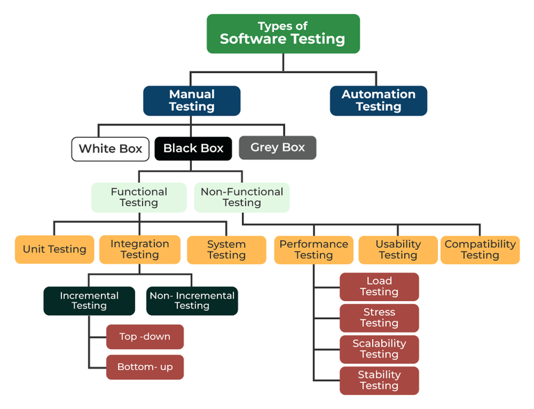
1. Functional Testing
- Purpose: To verify that the software functions according to specified requirements.
- Focus: Testing individual functions or features.
- Examples: Unit testing, integration testing, system testing.
2. Non-Functional Testing
- Purpose: To evaluate non-functional aspects like performance, usability, and security.
- Focus: Testing qualities other than functionality.
- Examples: Performance testing, usability testing, security testing.
3. Manual Testing
- Purpose: Testers execute test cases manually without automation.
- Focus: Testing for human intuition, exploratory testing.
- Examples: Ad-hoc testing, exploratory testing, user acceptance testing.
4. Automated Testing
- Purpose: Test cases are automated using testing tools and scripts.
- Focus: Repeated execution of test cases with precision.
- Examples: Selenium for web testing, JUnit for unit testing.
5. Black Box Testing
- Purpose: Focuses on testing the functionality of the software without knowing its internal code.
- Focus: Input-output behavior and external functionality.
- Examples: Functional testing, acceptance testing.
6. White Box Testing
- Purpose: Examines the internal code and logic of the software.
- Focus: Testing the internal structure and algorithms.
- Examples: Unit testing, code coverage analysis.
7. Integration Testing
- Purpose: To test interactions between different modules or components.
- Focus: Detecting interface issues and module collaboration.
- Examples: Top-down integration, bottom-up integration.
8. Regression Testing
- Purpose: Ensures that recent code changes have not adversely affected existing functionalities.
- Focus: Re-testing affected areas after code changes.
- Examples: Automated test suites, continuous integration.
9. User Acceptance Testing (UAT)
- Purpose: Involves end-users to validate that the software meets their requirements.
- Focus: Testing from the user's perspective.
- Examples: Alpha testing, beta testing.
10. Load Testing
- Purpose: Evaluates the system's ability to handle expected load levels.
- Focus: Assessing performance under expected load conditions.
- Examples: Stress testing, scalability testing.
11. Security Testing
- Purpose: Identifies vulnerabilities and ensures data protection.
- Focus: Identifying security risks and threats.
- Examples: Penetration testing, vulnerability scanning.
12. Usability Testing
- Purpose: Assesses the software's user-friendliness.
- Focus: Evaluating the user interface and overall user experience.
- Examples: User-centered design testing, heuristic evaluation.
16. Give the various approaches of Black box testing
Ans16
Black Box Testing is a software testing technique that focuses on testing the functionality of a software application without knowledge of its internal code or structure. It is based on the software's specifications and requirements. There are several approaches to conducting Black Box Testing:
-
Equivalence Partitioning:
- This approach divides the input domain of a system into groups or partitions that are expected to exhibit similar behavior.
- Test cases are designed to cover each partition, ensuring that representative inputs from each group are tested.
- It helps in identifying common input errors and potential issues.
-
Boundary Value Analysis (BVA):
- BVA focuses on testing values at the boundaries of input domains, as these are often more likely to cause errors.
- Test cases are designed to test values at the upper and lower boundaries, just beyond the boundaries, and at the exact boundaries.
- It helps detect off-by-one errors and issues related to boundary conditions.
-
Decision Table Testing:
- In this approach, test cases are derived from a decision table that defines possible combinations of input conditions and corresponding actions or outcomes.
- Test cases are created to cover all possible combinations, ensuring comprehensive testing of decision-making logic.
- It is particularly useful for complex business rules.
-
State Transition Testing:
- State Transition Testing is used for systems that have states or modes that change based on specific conditions or events.
- Test cases are designed to cover transitions between different states, including valid and invalid transitions.
- It is commonly used in testing software with user interfaces and interactive components.
-
Use Case Testing:
- This approach involves designing test cases based on the various use cases defined for the software.
- Test cases simulate real-world scenarios by following the sequences of actions specified in use cases.
- It helps ensure that the software functions as expected in typical user interactions.
-
Error Guessing:
- Error Guessing is an informal approach where testers use their intuition, experience, and knowledge to identify potential error-prone areas in the software.
- Test cases are derived based on educated guesses about where defects might occur.
- It is useful for finding defects that may not be covered by other formal techniques.
-
Ad Hoc Testing:
- Ad Hoc Testing is an unstructured and exploratory approach where testers perform testing without a predefined test plan.
- Testers use their creativity and domain knowledge to interact with the software and identify issues.
- It is often used for quick checks and initial testing.
17. Discuss the various techniques of White box testing
Ans17
White Box Testing, also known as Structural Testing or Glass Box Testing, focuses on examining the internal structure and logic of a software application. Testers have access to the source code and use this knowledge to design test cases that ensure the code functions correctly. There are several techniques employed in White Box Testing:
1. Statement Coverage
- Description: Statement coverage, also known as line coverage, aims to test every executable statement in the code. Test cases are designed to ensure that each line of code is executed at least once during testing.
- Use: It helps identify unexecuted code segments, increasing code coverage.
2. Branch Coverage
- Description: Branch coverage, or decision coverage, ensures that every possible branch or decision point in the code is tested. It aims to test all true and false conditions for if-else statements and loops.
- Use: It helps uncover logical errors and missed paths in the code.
3. Path Coverage
- Description: Path coverage is one of the most thorough techniques, aiming to test every possible path or route through the code. It considers all possible combinations of branches, loops, and conditions.
- Use: It helps identify complex interdependencies and ensures comprehensive testing.
4. Condition Coverage
- Description: Condition coverage focuses on testing various conditions within code, such as multiple conditions within a single statement (e.g., "if (A && B)"). It ensures that all possible combinations of conditions are tested.
- Use: It helps detect issues related to condition evaluation and logical operators.
5. Loop Coverage
- Description: Loop coverage targets loops within the code, ensuring that loops execute zero, once, and multiple times. It tests loop boundaries, including the minimum and maximum iterations.
- Use: It helps identify problems related to loop termination and iteration.
6. Data Flow Testing
- Description: Data Flow Testing examines how data is manipulated and propagated within the code. Test cases are designed to explore data dependencies, variable definitions, and usage.
- Use: It uncovers issues related to data integrity, uninitialized variables, and data inconsistencies.
7. Mutation Testing
- Description: Mutation Testing involves intentionally introducing small changes (mutations) into the source code to create faulty versions. Test cases are then applied to detect if the mutations are caught by the testing process.
- Use: It assesses the effectiveness of the test suite by measuring its ability to detect introduced faults.
18. Elaborate the functional and nonfunctional testing
Ans18
Functional Testing
Functional Testing is a type of software testing that focuses on verifying that a software application's functions and features work as intended and meet the specified requirements. It primarily assesses whether the software performs its intended tasks correctly. Key points about Functional Testing include:
- Objective: The primary objective of functional testing is to ensure that the software behaves according to the functional specifications and requirements provided.
- Scope: It involves testing individual functions or features of the software by providing inputs and checking whether the expected outputs match the actual outputs.
- Black Box Testing: Functional testing is often conducted as a black-box testing technique, where the tester is unaware of the internal code and focuses on the externally observable behavior.
- Types: Common types of functional testing include Unit Testing, Integration Testing, System Testing, and User Acceptance Testing (UAT).
- Test Cases: Functional test cases are designed based on functional specifications and use cases to validate the software's functionality.
- Validation: It ensures that the software meets the needs of end-users and functions correctly in various scenarios.
Non-Functional Testing
Non-Functional Testing, on the other hand, evaluates the non-functional aspects of a software application, such as performance, reliability, usability, security, and scalability. It assesses how well the software performs under various conditions beyond its core functionality. Key points about Non-Functional Testing include:
- Objective: Non-functional testing aims to assess the software's performance, reliability, and other quality attributes that affect the user experience.
- Scope: It goes beyond the core features and examines aspects like response time, load handling, security vulnerabilities, and user-friendliness.
- Types: Non-functional testing encompasses various types, including Performance Testing, Load Testing, Security Testing, Usability Testing, and Scalability Testing.
- Testing Environments: Non-functional testing often requires specialized testing environments and tools to simulate real-world conditions and measure performance metrics.
- Criteria: Non-functional testing sets criteria and benchmarks to determine whether the software meets performance standards and can handle expected user loads.
- Validation: It validates that the software not only works correctly but also delivers a satisfactory user experience.
19. Discuss the format of test case for any application
Ans19
A test case is a detailed set of conditions or steps that are used to test specific functionalities or aspects of a software application. A well-structured test case helps in systematic testing and ensures that the application behaves as expected. Below is the typical format of a test case for any application:
Test Case Identifier
- Test Case ID: A unique identifier or name for the test case, often in the form of a code or label.
Test Case Description
-
Title: A brief and descriptive title that summarizes the purpose of the test case.
-
Objective: A clear statement of the test's objective, explaining what aspect of the application is being tested.
Preconditions
- Preconditions: Any prerequisites or conditions that must be met before executing the test case. For example, login credentials, specific configurations, or data setup.
Test Steps
-
Test Steps: A numbered list of detailed steps to be followed to execute the test. Each step should be clear, concise, and actionable.
-
Step 1: Describe the action to be taken, such as "Open the application."
- Step 2: Specify any inputs or data to be provided, e.g., "Enter username and password."
- Step 3: Define the expected outcome or result, like "User should be logged in successfully."
Expected Results
-
Expected Results: Clear and unambiguous statements that describe the expected outcomes or behaviors of the application after each step or action.
-
"The application's login page should open."
- "The user should see their dashboard."
- "The submitted form data should be saved to the database."
Test Data
- Test Data: Any specific data or values used during the test case execution. This may include sample inputs, test files, or data sets.
Test Environment
- Test Environment: Specify the testing environment or configuration in which the test case is to be executed, including hardware, software, and network settings.
Test Execution
- Execution Steps: Provide detailed instructions on how to execute the test case, including any special considerations or parameters.
Actual Results
- Actual Results: A section where the tester records the actual outcomes or behaviors observed during test execution. This should be filled in after executing the test.
Pass/Fail Criteria
- Pass/Fail Criteria: Clearly define the criteria for determining whether the test case has passed or failed. This is usually based on a comparison between actual and expected results.
Notes
- Notes: Any additional notes, comments, or observations related to the test case or test execution.
Test Case Status
- Status: Indicate the current status of the test case (e.g., Pass, Fail, In Progress).
Test Case Author
- Author: Identify the person or team responsible for creating the test case.
Date
- Date: Record the date when the test case was created or last modified.
Attachments
- Attachments: Include any relevant attachments, such as screenshots, documents, or logs, to support the test case.
Review and Approval
- Review and Approval: If applicable, document the review and approval process for the test case, including the names of reviewers and approvers.
20.Discuss Regression testing and Various types of functional testing
Ans20
Regression Testing is a type of software testing that focuses on ensuring that changes or enhancements made to a software application do not negatively impact the existing functionality of the system. It is crucial for maintaining the reliability and stability of the software throughout its development lifecycle. Key points about Regression Testing include:
-
Purpose: The primary purpose of Regression Testing is to identify and detect any unintended side effects or defects introduced as a result of code changes, updates, or enhancements.
-
Scope: Regression Testing covers the re-execution of test cases that have been previously executed to ensure that existing functionalities are not broken due to modifications.
-
Types: There are several types of Regression Testing, including:
- Unit Regression Testing: Focused on testing individual units or components of the software.
- Partial Regression Testing: Involves testing only the areas of the software affected by recent changes.
- Complete Regression Testing: Encompasses testing the entire application to ensure overall functionality remains intact.
-
Selective Regression Testing: Concentrates on specific critical areas impacted by code changes.
-
Automation: Automation tools are often employed in Regression Testing to efficiently re-run test cases and identify any deviations from the expected behavior.
Functional Testing is a type of software testing that evaluates the functionality of a software application by verifying whether it performs its intended functions correctly. It focuses on the "what" the software does rather than "how" it does it. Different types of Functional Testing include:
-
Unit Testing:
- Tests individual units or components of the software.
- It is typically performed by developers during the coding phase.
- Aimed at verifying that each unit functions as intended.
-
Integration Testing:
- Focuses on testing the interactions between different units or modules.
- Ensures that integrated components work together as expected.
-
System Testing:
- Evaluates the entire software system as a whole.
- Verifies that the system meets its functional requirements.
- It may include test scenarios, user acceptance testing, and end-to-end testing.
-
User Acceptance Testing (UAT):
- Conducted by end-users or stakeholders.
- Validates that the software meets user expectations and business requirements.
-
Smoke Testing:
- A preliminary test to determine whether the software build is stable enough for more comprehensive testing.
- Focuses on critical functionalities.
-
Sanity Testing:
- A subset of Regression Testing.
- Verifies that specific functionalities or code changes have not introduced critical defects.
-
Alpha and Beta Testing:
- Alpha Testing is performed by the internal development team before the software is released to external users.
- Beta Testing involves external users testing the software in a real-world environment.
-
Exploratory Testing:
- Testers explore the software without predefined test cases.
- Focuses on uncovering unexpected issues.
-
Compatibility Testing:
- Ensures that the software functions correctly on various platforms, browsers, and devices.
Functional Testing is essential for ensuring that a software application meets its intended purpose and delivers a reliable user experience.
References
- https://creately.com/blog/diagrams/uml-diagram-types-examples/